Assembly Drawings 271 Five piston rings 4 are positioned in the piston 1. Four at the top and one at the bottom.

Design Technical Drawings Of Nonexistent Internal Combustion Engine Piston Clipping Path Technical Drawing Stock Photos Design Drawings
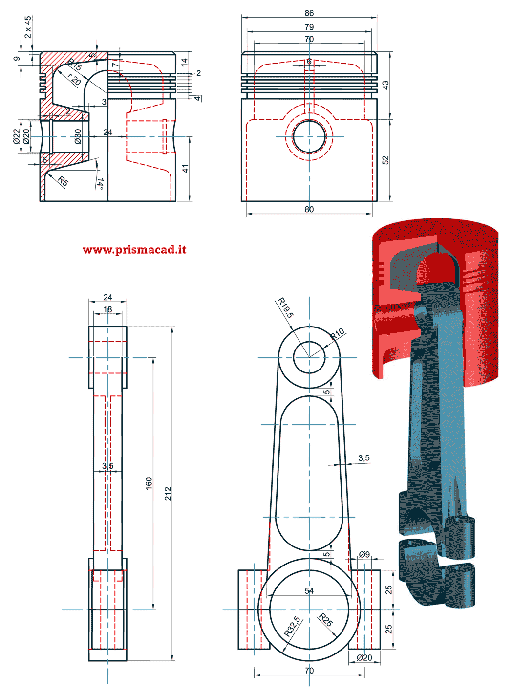
Piston and connecting rod assembly drawing with dimensions.
. The Radial Engine assembly will be created in two parts one will be the subassembly and the other will be the main assembly. 3 4421 1024 Piston Rod Assembly 1 80 rod 4 4421 1026 Mounting Eye 1 5 4421 0595 End Cap 1 6 4421 1334 Seal Housing 1. PRODUCTION DRAWING and practice for the connecting rod not shown in figure.
For other parts and assembly contact me. 9 72400-576 1 Servo Piston Assembly parts list on page 6 10 72400-585 1 Servo Piston Follower 11 72400-620 1 Cover Plate 12 72400-621 2. In general a slider crank transmits motion generated by the linear displacement of the piston by a working fluid to rotational.
Introduction 1The assembly of the piston connecting rod and crank shaft in an engine behaves like a mechanism during the working of the engine. A STEPS TO DRAW ASSEMBLY DRAWING FROM DETAILS DRAWING- 1. H 545mm.
Dimensions to indicate range of motion or overall size of assembly for reference purposes. S3L engine pdf manual download. 1231 Design Assembly Drawing When a machine is designed an assembly drawing or a design layout is first drawn to clearly visualise the performance shape and clearances of various parts comprising the machine.
The tribological considerations in the contacts formed by the piston skirt piston rings and cylinder liner or bore have attracted much attention over several decades not least indicated by the large number of articles published on this topic in recent years. 2 Bore or outside diameter of piston D 57mm Thickness of piston headt. Oil or scraper ring prevents the lubricating oil from enteringthe combustion chamber.
The piston skirt is the cylindrical valve of the piston. CHAPTER - 06 ASSEMBLY AND DETAILS DRAWING. We WILL send Standard Size unless you inform us of another size.
The information contained in this drawing is the sole property of university of idaho me department. Radial Engine Assembly 1 In this project you will create the Radial Engine assembly shown in Figures 1 and 2. This will help in understanding the functional requirements of individual parts and their location.
Are used for parts catalogs and installation manuals or for production if the assembly is simple. Proprietary and confidential material. C Temperature at the edge of piston head T.
Figure 33 shows both inside and outside views of a four-stroke engine piston. 1232 Detailed Assembly Drawing It is usually made for simple machines comprising of a relatively smaller number of simple parts. 1-PistonRing Assembly - NOTE.
Understand the purpose principle of operation and field of application of the given machine. Steam engine crosshead assembly drawing pdf. Assembly Drawings must have a number of views to show how parts fit together.
For the connecting rod not shown in figure. Gearbox assembly drawing pdf Slider Crank Mechanism for Demonstration and. Final assembly drawn by.
HK 417 Piston Rod Assembly drawing. Apr 25 2013 The assembly of a piston cylinder connecting-rod and crankshaft is the classic form of the slider-crank mechanism. Figure 32 shows pistons used for two-stroke engines.
TAkyürek ME 114 Computer Aided Engineering Drawing II Assembly Drawing Exercises. Piston and connecting rod assembly drawing with dimensions. The piston receives combustion power first and then the connecting rod transmits the power through the piston pin.
Kinds of Assembly Drawings Pictorial assembly drawings Outline assembly drawings give general graphic description of the exterior shape. HK 417 Piston Rod Assembly drawing. Revision Drawing List.
C Maximum gas pressure p 15454Nmm. SECTION 6 - Parts Lists Assembly Drawings INDEX OF DRAWINGS AND PARTS LISTS FOR JOB NUMBER Reference. The piston rod 2 is secured to the crosshead block by.
Any reproduction in part or as a whole without the written permission of university of idaho me department is prohibited. Figure 34 illustrates an assembly comprising piston piston ring and piston pin. The piston rod 2 is secured to the crosshead block by means of the cotter 5.
Piston Connecting Rod Assembly Drawing 24 Download Mar 01 2022 Its meant for high-performance vehicles and can cost as much as 50 cents more per gallon. The assembly ensures reciprocating motion along a straight line for the piston rod and reciprocating cum oscillatory motion for the connecting rod. Section views to show how parts fit and to eliminate hidden detail.
Engine displacement Piston skirt Under square Crank web HyperMesh Ansys. Piston rings pressure of the gas on the cylinder wall 0042Nmm. Yet the steam-engine of to-day is three or four times as efficient as the engine of fifty years ago.
Piston Connecting Rod Assembly Drawing MITSUBISHI S3L SERVICE MANUAL Pdf Download ManualsLib View and Download Mitsubishi S3L service manual online. Piston drawing with dimensions Piston drawing with dimensions pdf. 108 Piston Assembly incd 110 4 D01A513B 134 Connecting Rod 4 D01-509A 109 Wrist Pin 4 TC-389B 135 Crankshaft Assembly 1 28326 110 Piston Ring Pack 1 set D01-337-8 137 Key 1 71383095 111 Cylinder Sleeve 4 D01-L505A 138 Bearing 1 58-96 112 Capscrew 16 50156 139 Motor Adapter 1 28314 113 Washer copper 24 D01-504 241 Reverse Valve Nut 1.
Thetop piston rings known as compression rings prevent leakage of gases from combustion chamberinto the crank case. 4 4-00 Valve Sub Assembly 1 49 5 5-00 Piston Sub Assembly 1 56 6 6-00 Stephenson Link Sub Assembly 1 60 7 7-00 Handle Sub Assembly 1 69 Marine Engine Project FILE NAME. Assembly Drawings must provide sufficient information to enable the assembly of a component.
Piston assembly drawing with dimensions. For other parts and assembly contact me. The dimensions of the components of the Radial Engine assembly are shown in Figures 3 through 6.
The weight of the Cast Iron piston is preventing the engine to operate at a higher speed. Temperature at the center of piston head T. Piston rod drawing sheet.
The EJ257 blocks the EJ257 engine had a 995 mm fused aluminum block and a spill of 790 mm to a capacity of 2457 cc.

Connecting Rod Mechanical Design Mechanical Engineering Design Autocad Isometric Drawing

Assembly And Details Machine Drawing Pdf Mechanical Design Mechanical Engineering Design Mechanical Projects

Resultado De Imagen De Detailed Assembly Drawing Mechanical Design Mechanical Engineering Design Engineering Design

Machine Drawing Connecting Rod Mechanical Engineering Design Blueprint Drawing Mechanical Design

Piston Head Detailed Drawing Engineering Google Search Mechanical Design Mechanical Engineering Mechanical Engineering Design

Piston Autocad Isometric Drawing Mechanical Engineering Design Isometric Drawing

Piston Rod Drawing Sheet Drawing Sheet Mechanical Engineering Design Mechanical Design
Disegno Meccanico Biella Pistone Connecting Rod Piston Mechanical Engineering Design Mechanical Design Engineering Design
0 comments
Post a Comment